

|
|
| Click on image for video | Click on image for full schematic |
The aim of this project is to build a prototype replacement for the Chronomix cc3000 race clock controller board.
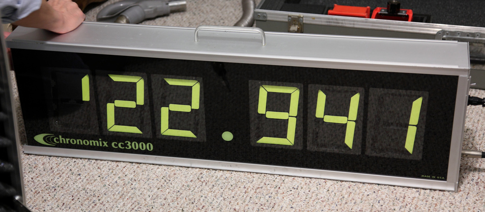
The Chronomix cc3000 race clock uses signalex flip digits. There are several versions of this old clock design. It may have five or six digits on a side. Some clocks are double sided, others are single sided. The glass face may be replaced to show the decimal point at different locations. AFAIK, all chronomix clocks use the six inch signalex digit.
My inspection of the original control board led me to believe that the original control board is unmaintainable. The current chronomix company no longer supports flip digit clocks. Expert Timing Systems offers a repair service and possibly a replacement control board. But there would be some advantages to upgrading this clock using arduino (e.g. 900 MHz radio communication with other timing devices).
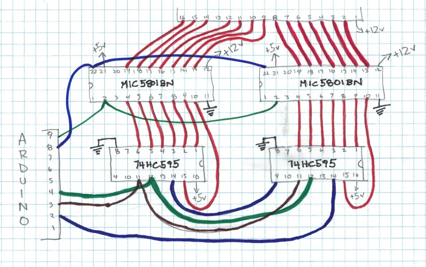
This project continues with the design used in previous experiments. Each signalex digit requires about 120mA at 12v to flip, which is provided on 14 wires by a pair of MIC5801BN current drivers. There are six digits, requiring a total of twelve mic5801bn driver chips. The driver chips have latched input. This means that they read and store the logic levels of the input lines when the STROBE pin transitions from LOW to HIGH. This means that we can use just the two 74hc595 chips from the original design and wire their fourteen output pins to the input pins of every digit. I will call these fourteen wires the data bus. By controlling the STROBE pins independently, we instruct individual digits to read the data bus.
In addition to the STROBE pin, each mic5801bn has an OUTPUT ENABLE pin. When this pin is grounded, the mic5801bn output is enabled. When the OUTPUT ENABLE pin is HIGH, output is disabled. The vanes of the signalex digit only require current when the number changes, which only takes 150 ms (determined experimentally). So most of the time the OUTPUT ENABLE pins will be set to HIGH. When it is time to change the digit, the process works like this:
There are six digits, each digit requires a STROBE and OUTPUT ENABLE control, so there are a total of twelve wires in the control bus.
The arduino has a built in clock but the arduino clock is not very accurate. Also, because the race clock may be used across a wide range of temperatures, the clock must be temperature compensated. Therefore I have added the DS3231 temperature compensated real time clock, which communicates with the arduino using I2C (or "2 wire protocol") on arduino pins 20 and 21. The DS3231 provides a stable clock output with frequency 32.768KHz on arduino pin 3. The arduino can be instructed to generate an interrupt whenever it receives a "tick" on pin 3. By counting ticks, the race clock has an accuracy better than 1 ms. The accuracy of the display is only +/- 0.5 s so 1 ms accuracy on the internal clock is good enough.
The clock comes with a 27 key membrance keypad. Internally, this keypad uses a 14 conductor edge connector. The keypad is a simple row/column arrangement EXCEPT FOR THE TOP RIGHT KEY LABELLED ‘CLEAR MEMORY’. The CLEAR MEMORY key has its own two conductors, numbered 13 and 14. The diagram below shows how the conductors are assigned to rows and columns. AFAIK conductor 7 is not used.
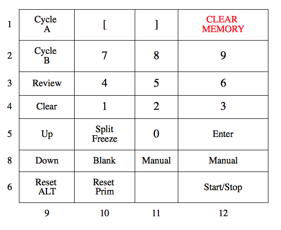
This keypad can be implemented using the arduino keypad library. I assigned the rows to arduino pins 31, 32, 33, 34, 35, 37, and 36. The columns are assigned to pins 41, 42, 43, and 44.
For my experiment I relabelled some of the keys using yellow electrical tape. I relabelled the Cycle A , Cycle B, and Review buttons, respectively, to CLOCK, TIME, and TEMP.
There are four modes: race clock, time of day clock, temperature and blank. Press the Cycle A button for race clock. Cycle B for time of day clock. Review for temperature, and Blank for Blank.
Use the Start/Stop button to start and stop the race clock. It doesn't matter what mode the display is in.
To set the race clock to a certain time, press the Up key for Set. The display should change to zeros. Press a number key. That number will appear in the rightmost digit. Press another number. The rightmost digit will move one digit to the left, and the new number will appear in the rightmost digit. Etc. When the display is set correctly, press the Enter key. Then press start to start the clock.
#include <SPI.h>
#include <Keypad.h>
#include <Wire.h>

/*
 *   Six digit clock with keypad and rtc
 *
 *   note: way too many globals
 *
 *   (c) A. Howlett, Feb 2014
 */

/*
 *   Chronomix clocks ship with 5 or 6 digits.
 *   These clocks may be double sided, but the two sides of the clock
 *     are wired in parallel.
 *   Energize time for the coil is 150ms.
 */


#define NUMBER_OF_DIGITS 6
#define COIL_ENERGIZE_TIME 150

/*
 *   Modes:   0 - nothing, blank display
 *            1 - race clock
 *            2 - time of day clock
 *            3 - temperature
 *
 *    start in race clock mode with the clock off
 */

#define MODE_NOTHING        0
#define MODE_RACECLOCK      1
#define MODE_TIMEOFDAYCLOCK 2
#define MODE_TEMPERATURE    3
#define MODE_PROGRAM        4

byte activeMode = MODE_RACECLOCK;
boolean raceClockRunning = false;

/*
 *   The DS3231 rtc communicates on i2c bus using id 0x68
 *   Reading the DS3231 32.768kHz clock on mega pin 3
 *   Reading clock frequency 32768 Hz
 *
 *   The interupt routine counts ticks using the countTicks variable
 *   When countTicks reaches 32768, interrupt routine sets secondsElapsed to TRUE
 *
 *   countTicks and secondsElapsed are for race clock time.
 *   when race clock is running the display updates when the race time seconds roll
 *       (even if the clock is in another mode, the display updates according to race
 *        clock time)
 *   but if the race clock is stopped, then countTicks are not increased and secondsElapsed
 *     never becomes TRUE. We still need the display to update in time of day mode and temperature
 *     mode. So when race clock is stopped clock switches to secondaryCountTicks and secondaryElapsed
 *     secondaryCountTicks and secondaryElapsed are ALWAYS updated, NEVER stopped, so there is
 *     no chance of the clock falling into a state where the display is not updated and/or the
 *     mode cannot be changed.
 */

#define DS3231_I2C_ADDRESS 0x68
#define INTERRUPT_PIN 3
#define FREQUENCY 32768

volatile long countTicks = 0;
volatile boolean secondElapsed = false;
volatile long secondaryCountTicks = 0;
volatile boolean secondaryElapsed = false;

/*
 *    using SPI function calls, so only slave select required
 *
 *    for mega 2560 :
 *                    byte misoPin = 50;
 *                    byte mosiPin = 51;
 *                    byte spiClockPin = 52;
 *                    byte slaveSelectPin = 53;
 *
 *     SPI operates at 4MHz
 */

byte slaveSelectPin = 53;

/*
 *  each mic5801 has a strobe pin and an enable pin
 *  the input control voltages are applied, mic5801 reads the input when the strobe
 *     pin goes high.
 *  output is enabled when enable pin goes low.
 *  only need to enable for 150ms (coil energize time)
 */

byte mic5801StrobePin[NUMBER_OF_DIGITS] = { 5,7,9,11,13,23};
byte mic5801EnablePin[NUMBER_OF_DIGITS] = { 4,6,8,10,12,22};

/*
 * remember the last number sent to signalex.
 * (if we write the same number that's already shown, don't
 *  need to change anything, can save battery)
 */

byte lastNumbersSentToSignalex[NUMBER_OF_DIGITS][2] = {{0,0},{0,0},{0,0},{0,0},{0,0},{0,0}};

/*
 *   each segment has two coils: one to make the segment show yellow, another to make it show black
 *
 *  codes:
 *    0 to 9 are 0 to 9
 *    10 to 15 are hexadecimal, A,b,c,d,E,F
 *   16 -> all black
 *   17 -> negative sign
 *
 */

byte numbersToSignalex[17][2]= {
  {250, 16},
  {96, 188},
  {214, 34},
  {244, 40},
  {108, 140}, // 140/2 = 70 = 100 0110
  {188, 72},
  {190, 64},
  {224, 60},
  {254, 0},
  {252, 8},
  {238, 4},
  {62, 192},
  {154, 82},
  {118, 160},
  {158, 66},
  {142, 70},
  {0, 254}
};


/*
 * keypad info
 */

const byte ROWS=7;
const byte COLS=4;

/*   A -> switch to Race Clock mode (implemented)
 *   B -> switch to Time of Day Clock (implemented)
 *   C -> switch to Temperature (implemented)
 *   0-9 -> 0-9
 *   # -> Clear Memory
 *   u -> up
 *   d -> down
 *   M -> Manual
 *   S -> Start/Stop race clock (implemented)
 *   f -> force refresh all digits (implemented)
 *   R -> reset race clock (implemented)
 *   b -> blank mode (implemented)
 */

char keys[ROWS][COLS] = {
  {'A',' ',' ',' '},
  {'B','7','8','9'},
  {'C','4','5','6'},
  {'P','1','2','3'},
  {'u','f','0','E'},
  {'d','b',' ','M'},    // remember line order is 1,2,
  {'f','R',' ','S'},
};

byte rowPins[ROWS] = {31,32,33,34,35,37,36}; //connect to the row pinouts of the keypad
byte colPins[COLS] = {41,42,43,44}; //connect to the column pinouts of the keypad

Keypad keypad = Keypad( makeKeymap(keys), rowPins, colPins, ROWS, COLS );

/* these variables are used to program the clock */

int programDigit[NUMBER_OF_DIGITS];

struct raceTime {
  byte ones;
  byte tens;
  byte minutes;
  byte tensMinutes;
  byte hours;
  byte tensHours;
} raceTime;

struct TimeOfDay {
  byte seconds, minutes, hours, day, date, month, year;
} timeOfDay;

void setup () {

  //  this is for debug output to computer
  Serial.begin(9600);

  //  initialize 5801 (disable it)
  for (int i; i<NUMBER_OF_DIGITS; i++) {
    pinMode(mic5801EnablePin[i], OUTPUT);
    pinMode(mic5801StrobePin[i], OUTPUT);
    digitalWrite(mic5801EnablePin[i], HIGH);
    digitalWrite(mic5801StrobePin[i], LOW);
  }

  // initialize keypad
  keypad.addEventListener(keypadEventHandler);  // Add an event listener.
  keypad.setHoldTime(500);               // Default is 1000mS
  keypad.setDebounceTime(100);           // Default is 50mS

  // initialize SPI
  SPI.begin();
  SPI.setBitOrder(MSBFIRST);

  // initialize display
  for (int i=0; i<NUMBER_OF_DIGITS; i++) {
    setSignalex(i, numbersToSignalex[0]);
    delay(COIL_ENERGIZE_TIME);
  }
  raceTime.ones=0; raceTime.tens=0; raceTime.minutes=0; raceTime.tensMinutes=0; raceTime.hours=0; raceTime.tensHours=0;

  // register interrupt function to 32768 Hz rtc clock
  pinMode(INTERRUPT_PIN, INPUT);
  digitalWrite(INTERRUPT_PIN, HIGH); // internal pull up isn't good enough at 32kHz - need to use a 3.3k pull up resistor
  attachInterrupt(1, ds3231SqwInterruptHandler, FALLING);

  // initialize i2c comms for rtc
  Wire.begin();
}

/*
 *  main loop
 *  ---------
 *
 */

void loop () {
  char key=keypad.getKey();
  if (key) Serial.println(key);
  if ( raceClockRunning && secondElapsed ) {
    secondElapsed = false;
    incrementRaceTime();
    updateDigitsByMode();
  }
  if ( !raceClockRunning && secondaryElapsed ) {
    secondaryElapsed = false;
    updateDigitsByMode();
  }
}

void updateDigitsByMode() {
    switch (activeMode) {
      case MODE_NOTHING:
        showBlankAllDigits();
        break;
      case MODE_RACECLOCK:
        showRaceTime();
        break;
      case MODE_TEMPERATURE:
        showTemperature();
        break;
      case MODE_TIMEOFDAYCLOCK:
        showTimeOfDay();
        break;
      case MODE_PROGRAM:
        showProgram();
        break;
    }
}

void showTemperature() {
  int temperature = get3231Temp();
  int digit1=16, digit2=16, digit3=16;
  boolean negative = false;

  if (temperature<0) {
    negative = true;
    temperature *= -1;
  }

  digit1 = temperature % 10;
  digit2 = temperature / 10;
  if (digit2 == 0 && negative) digit2 = 17;
  if (digit2 > 0 && negative) digit3 = 17;
  Serial.print(temperature);
  Serial.print(" , ");
  Serial.print(negative);
  Serial.print(" , ");
  Serial.print(digit1);
  Serial.print(" , ");
  Serial.println(digit2);

  setSignalex(0, numbersToSignalex[12]);
  setSignalex(1, numbersToSignalex[16]);
  setSignalex(2, numbersToSignalex[digit1]);
  setSignalex(3, numbersToSignalex[digit2]);
  setSignalex(4, numbersToSignalex[digit3]);
  setSignalex(5, numbersToSignalex[16]);
}

int get3231Temp()
{
  //temp registers (11h-12h) get updated automatically every 64s
  float temp3231 = 99;
  byte tMSB, tLSB;

  Wire.beginTransmission(DS3231_I2C_ADDRESS);
  Wire.write(0x11);
  Wire.endTransmission();
  Wire.requestFrom(DS3231_I2C_ADDRESS, 2);

  if(Wire.available()) {
    tMSB = Wire.read(); //2's complement int portion
    tLSB = Wire.read(); //fraction portion
    temp3231 = ((((short)tMSB << 8) | (short)tLSB) >> 6) / 4.0; // Allows for readings below freezing - Thanks to Coding Badly
  }

  Serial.print("Temperature: "); Serial.println(temp3231);

  return (int) temp3231;
}

void showTimeOfDay() {
  get3231Date();
  int digit0=16, digit1=16, digit2=16, digit3=16, digit4=16, digit5=16;

  digit2 = timeOfDay.minutes % 10;
  digit3 = timeOfDay.minutes / 10;
  digit4 = timeOfDay.hours % 10;
  digit5 = timeOfDay.hours / 10;
  if ( digit5 == 0 && digit4 ==0 ) { digit5 = 1 ; digit4 = 2; } // display midnight to 1am as 12
  if ( digit5 == 0 && digit4 !=0 ) digit5 = 16;                 // don't show leading zero

  setSignalex(0, numbersToSignalex[digit0]);
  setSignalex(1, numbersToSignalex[digit1]);
  setSignalex(2, numbersToSignalex[digit2]);
  setSignalex(3, numbersToSignalex[digit3]);
  setSignalex(4, numbersToSignalex[digit4]);
  setSignalex(5, numbersToSignalex[digit5]);
}

void get3231Date()
{
  // send request to receive data starting at register 0
  Wire.beginTransmission (DS3231_I2C_ADDRESS);
  Wire.write (0x00); // start at register 0
  Wire.endTransmission();
  Wire.requestFrom(DS3231_I2C_ADDRESS, 7); // request seven bytes

  if ( Wire.available() ) {
    timeOfDay.seconds = Wire.read();
    timeOfDay.minutes = Wire.read();
    timeOfDay.hours   = Wire.read();
    timeOfDay.day     = Wire.read();
    timeOfDay.date    = Wire.read();
    timeOfDay.month   = Wire.read();
    timeOfDay.year    = Wire.read();

    timeOfDay.seconds = ((timeOfDay.seconds & B11110000)>>4)*10 + (timeOfDay.seconds & B00001111); // convert BCD to decimal
    timeOfDay.minutes = ((timeOfDay.minutes & B11110000)>>4)*10 + (timeOfDay.minutes & B00001111); // convert BCD to decimal
    timeOfDay.hours   = ((timeOfDay.hours & B00010000)>>4)*10 + (timeOfDay.hours & B00001111);     // convert BCD to decimal
/*
 *  this clock doesn't display day, date, month or year
 *
    day     = (day & B00000111); // 1-7
    date    = (((date & B00110000)>>4)*10 + (date & B00001111)); // 1-31
    month   = (((month & B00010000)>>4)*10 + (month & B00001111)); //msb7 is century overflow
    year    = (((year & B11110000)>>4)*10 + (year & B00001111));
 */
  }
}


void incrementRaceTime() {
  raceTime.ones++;
  if (raceTime.ones == 10) {
    raceTime.ones = 0;
    raceTime.tens++;
    if (raceTime.tens == 6) {
      raceTime.tens = 0;
      raceTime.minutes++;
      if (raceTime.minutes == 10) {
        raceTime.minutes = 0;
        raceTime.tensMinutes++;
        if (raceTime.tensMinutes == 6) {
          raceTime.tensMinutes = 0;
          raceTime.hours++;
          if (raceTime.hours == 10) {
            raceTime.hours = 0;
            raceTime.tensHours++;
          }
          if ( (raceTime.tensHours == 2) && (raceTime.hours == 4) ) {
            raceTime.hours = 0;
            raceTime.tensHours = 0;
          }
        }
      }
    }
  }
}

void showRaceTime() {
    setSignalex(0, numbersToSignalex[raceTime.ones]);
    setSignalex(1, numbersToSignalex[raceTime.tens]);
    setSignalex(2, numbersToSignalex[raceTime.minutes]);
    setSignalex(3, numbersToSignalex[raceTime.tensMinutes]);
    setSignalex(4, numbersToSignalex[raceTime.hours]);
    setSignalex(5, numbersToSignalex[raceTime.tensHours]);
}

/*
 *   SIGNALEX DISPLAY ROUTINES
 *
 *
 */

void setSignalex(int digit, byte value[2]) {
  /* if digit is same as last digit sent to signalex, then don't need to change anything */
  /* note: sometimes a segment fails to flip. the refresh key on the keypad will force all
   *       digits to redraw on the next secondElapsed.
   */
  if ( (lastNumbersSentToSignalex[digit][0] == value[0]) && (lastNumbersSentToSignalex[digit][1] == value[1]) ) {
    Serial.println("setSignalex no changes necessary");
    return;
  }
  /*  we can save power by comparing the digit currently displayed with
   *  the new digit and only energizing the coils that need to change
   *  (otherwise, we might energize coils that are already in the
   *   desired position, wasting power)
   */
  byte valuesSentToShiftRegister[2];
  valuesSentToShiftRegister[0]=(value[0] ^ lastNumbersSentToSignalex[digit][0]) & value[0];
  valuesSentToShiftRegister[1]=(value[1] ^ lastNumbersSentToSignalex[digit][1]) & value[1];
  lastNumbersSentToSignalex[digit][0] = value[0];
  lastNumbersSentToSignalex[digit][1] = value[1];
  /*
   *  Use SPI to write the values to the two shift registers.
   */
  writeValuesToShiftRegistersUsingSPI(valuesSentToShiftRegister);
  /*
   *  The output of the shift registers is sent to ALL the current drivers (MIC5801BN)
   *  But they only update their input registers when the strobe line goes HIGH
   *  We strobe only the digit to which we want to write the new values.
   *  strobeMIC5801 also enables those two line drivers to send current to the coils
   */
  strobeMIC5801(digit);
}

/*
 *  send values to shift registers using SPI.
 *  take the shift registers offline while the
 *  values are shifting to prevent intermediate
 *  shift results from appearing on the outputs
 *  take HIGH when all bits are in correct position
 */

void writeValuesToShiftRegistersUsingSPI(byte value[2]) {
  digitalWrite(slaveSelectPin, LOW);
  SPI.transfer(value[0]);
  SPI.transfer(value[1]);
  digitalWrite(slaveSelectPin, HIGH);
}

/*
 *  void strobeMIC5801()
 *
 *  mic5801bn strobe pin must be set to high in order for the input
 *  levels on the input pins to be recorded in the internal registers.
 *
 *  mic5801bn enable pin must be set to LOW in order for the output
 *  pins to be enabled (in accordance with the values strobed to internal registers)
 *
 *  according to documentation, the 6 inch signalex digit requires 90ms of current
 *  however in practice I found 150ms to be required.
 */

void strobeMIC5801(int i) {
  digitalWrite(mic5801StrobePin[i], HIGH);
  delay(1);
  digitalWrite(mic5801StrobePin[i], LOW);
  digitalWrite(mic5801EnablePin[i], LOW);
  delay(COIL_ENERGIZE_TIME);  // energize the coils for 150ms, 90ms should do but this signalex might be defective
  digitalWrite(mic5801EnablePin[i], HIGH);
}

/*
 *  keypadEventHandler
 *
 */

 void keypadEventHandler(KeypadEvent key) {
   Serial.print("Caught kepad event\n");
    switch (keypad.getState()){
    case PRESSED:
      switch (key) {
        case 'A':
          activeMode = MODE_RACECLOCK;
          break;
        case 'B':
          activeMode = MODE_TIMEOFDAYCLOCK;
          break;
        case 'C':
          activeMode = MODE_TEMPERATURE;
          break;
        case 'P':
          activeMode = MODE_PROGRAM;
          clearProgramModeValues();
          break;
        case 'R':
          raceClockRunning = false;
          countTicks = 0;
          raceTime.ones=0;raceTime.tens=0;raceTime.minutes=0;raceTime.tensMinutes=0;raceTime.hours=0;raceTime.tensHours=0;
          for (int i=0; i<NUMBER_OF_DIGITS; i++) {
            setSignalex(i, numbersToSignalex[0]);
            delay(COIL_ENERGIZE_TIME);
          }
          break;
        case 'S':
          if (activeMode == MODE_RACECLOCK) raceClockRunning=!raceClockRunning; // stop/start only works in race clock mode
          break;

        case 'b':
          activeMode=MODE_NOTHING;
          break;
        case 'f':
          for (int i=0; i<NUMBER_OF_DIGITS; i++) {
            lastNumbersSentToSignalex[i][0] = 0;
            lastNumbersSentToSignalex[i][1] = 0;
          }
        case '0':
        case '1':
        case '2':
        case '3':
        case '4':
        case '5':
        case '6':
        case '7':
        case '8':
        case '9':
          addNewProgramDigit(key);
          break;

        case 'E':
          raceClockRunning = false;
          enterProgramAsRaceClock();
          activeMode = MODE_RACECLOCK;
          break;

      }
      break;

    case RELEASED:
        break;

    case HOLD:
        break;
    }
}

void enterProgramAsRaceClock() {
  raceTime.ones = programDigit[0];
  raceTime.tens = programDigit[1];
  raceTime.minutes = programDigit[2];
  raceTime.tensMinutes = programDigit[3];
  raceTime.hours = programDigit[4];
  raceTime.tensHours = programDigit[5];
}

void clearProgramModeValues() {
  programDigit[0]=0; programDigit[1]=0;
  programDigit[2]=0; programDigit[3]=0;
  programDigit[4]=0; programDigit[5]=0;
}


void addNewProgramDigit(char digit) {
  programDigit[5]=programDigit[4];
  programDigit[4]=programDigit[3];
  programDigit[3]=programDigit[2];
  programDigit[2]=programDigit[1];
  programDigit[1]=programDigit[0];
  programDigit[0] = digit - 48;
}

void showProgram(){
    setSignalex(0, numbersToSignalex[programDigit[0]]);
    setSignalex(1, numbersToSignalex[programDigit[1]]);
    setSignalex(2, numbersToSignalex[programDigit[2]]);
    setSignalex(3, numbersToSignalex[programDigit[3]]);
    setSignalex(4, numbersToSignalex[programDigit[4]]);
    setSignalex(5, numbersToSignalex[programDigit[5]]);
}

/*
 *   ds3231ClockInterruptHandler
 *
 *   this routine counts ticks on the 32768
 */

void ds3231SqwInterruptHandler(void) {
  secondaryCountTicks++;
  if ( secondaryCountTicks == 32768 ) {
    secondaryCountTicks = 0;
    secondaryElapsed = true;
  }
  if ( raceClockRunning ) {
    countTicks++;
    if (countTicks == 32768) {
      Serial.println("second");
      countTicks = 0;
      secondElapsed = true;
    }
  }
}

void showBlankAllDigits() {
    setSignalex(0, numbersToSignalex[16]);
    setSignalex(1, numbersToSignalex[16]);
    setSignalex(2, numbersToSignalex[16]);
    setSignalex(3, numbersToSignalex[16]);
    setSignalex(4, numbersToSignalex[16]);
    setSignalex(5, numbersToSignalex[16]);
}

void startUpTest() {
  int delay=100;
  int i0=0,i1=16,i2=16,i3=16,i4=0,i5=0;
  showBlankAllDigits();
  while (true) {
    i5=i4; i4=i3; i3=i2; i2=i1; i1=i0; i0++;
    if (i0>16) i0=16;
    setSignalex(0, numbersToSignalex[i5]);
    setSignalex(0, numbersToSignalex[i4]);
    setSignalex(1, numbersToSignalex[i3]);
    setSignalex(2, numbersToSignalex[i2]);
    setSignalex(3, numbersToSignalex[i1]);
    setSignalex(4, numbersToSignalex[i0]);
    if ( (i5+i4+i3+i2+i1+i0) == 80) break;
  }
}