
|
|
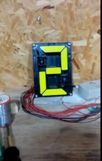
| Click on image for video | Click on image for full size |
This experiment improves the previous experiment in three ways:
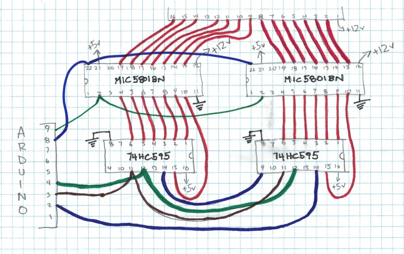
On the 74HC595 DIP package, output 0 is on pin 15 which is on the opposite side of the package compared to outputs 1-7 which are on pins 1-7. (See diagram from previous experiment.) This means that one line has to pass over or under the 74hc595 to get to the mic5801BN chip. Passing over or under the chip is possible, but why do that when we could use outputs 0-6 which are all on the correct side of the chip? So in this experiment 74hc595 pin 15 will be unconnected and pins 1-7 will be connected to the mic5801bn.
This means that we need to shift different bits to registers 0 and 1. Because we no longer use output 0, every bit will be shifted to the left. For instance, to display digit 0 we need to send 1111_1010 to register 0 and 0001_0000 to register 1. Shifting left one bit is the same as multiplying by 2. So in decimal, the new values would be 250 and 16. The table below shows the new register 0 and 1 values for each digit.
| Digit | Register 0 | Register 1 |
|---|---|---|
| 0 | 250 | 16 |
| 1 | 96 | 188 |
| 2 | 214 | 34 |
| 3 | 244 | 40 |
| 4 | 108 | 140 |
| 5 | 188 | 72 |
| 6 | 190 | 64 |
| 7 | 224 | 60 |
| 8 | 254 | 0 |
| 9 | 252 | 8 |
| A | 238 | 4 |
| b | 62 | 192 |
| C | 154 | 82 |
| d | 118 | 160 |
| E | 158 | 66 |
| F | 142 | 70 |
Serial Peripheral Interface (SPI) Bus is a synchronous serial data link that operates in full duplex mode. Arduino Uno includes SPI bus on pins 10 to 13. The SPI bus is implemented in hardware and is capable or running at full processor speed (16 MHz). Arduino Uno's SPI bus uses four pins, Master Out Serial In (MISO) on pin 12, Master In Serial Out (MOSI) on pin 11, Clock (SCK) on pin 13, and Slave Select on pin 10.
To control the shift register using SPI bus, connect MOSI (arduino uno pin 12) to Serial Data (74HC595 pin 14), connect Clock (arduino uno pin 13) to SRCLK (74HC595 pin 11), and connect Slave Select (arduino uno pin 10) to RCLK (74HC595 pin 12). In other words, MOSI is DATA, Clock is clock and Slave Select is LATCH.
Suppose a segment is displaying the number 0. Then it changes to 1. In the previous experiment, to make the one appear we energized the coil in segments B and C to show YELLOW. But yellow is already showing. So we don't need to energize those coils. Really, we only need to energize coils for segments that change. For instance, in the transition from 0 to 1, no segments are changing from black to yellow, so none of the orange wires need to be energized. But four segments are changing from yellow to black, so four red wires need to be energized.
Logically, considering only the orange wires, there are four conditions for a given segment. If the segment was originally black and stays black, then we don't need to energize the orange wire. If the segment was originally black and changes to yellow, then we need to energize the orange wire. If the segment was originally yellow and changes to black, then we don't need to energize the orange wire. If the segment was originally yellow and stays yellow, then we don't need to energize the orange wire. These four alternatives are summarized in the table below.
| Segment Originally Shows Yellow | Segment Changes to Yellow | Energize segment? |
|---|---|---|
| false | false | false |
| false | true | true |
| true | false | false |
| true | true | false |
We can express this relationship as a binary operation. If "Segment Originally Shows Yellow" is p and "Segment Changes to Yellow" is q, then the table below shows the desired logical operation: (p XOR q) AND p.
| p | q | p xor q | (p xor q) and p |
|---|---|---|---|
| false | false | false | false |
| false | true | true | true |
| true | false | true | false |
| true | true | false | false |
The same logic applies to register 1 and the red wires.
Maybe I'm just paranoid, but I want a switch which will force the signalex to energize all the segments, not just the segments that are changing. So I added a momentary button on Pin 2 of the arduino Uno and connected it to an interrupt. When I push the button, the interrupt function sets the last byte values to zero. This forces all segments to energize on the next write.
/* * signalex 2c * * this sketch improves on signalex2b by * energizing only coils required to change * * * the arduino pushes two bytes to a pair of shift * registers. the registers control the elements of * the signalex digit * * */ #includebyte setLastNumbersSentToSignalexToZeroInterrupt = 0; // int 0 is on pin 2 of the UNO // pins 3 to 7 unused byte mic5801EnablePin = 8; byte mic5801StrobePin = 9; byte slaveSelectPin = 10; byte mosiPin = 11; // miso is on pin 12 // SPI clock is on pin 13 byte lastNumbersSentToSignalex[2] = { 0, 0 }; byte numbersToSignalex[16][2]= { {250, 16}, {96, 188}, {214, 34}, {244, 40}, {108, 140}, {188, 72}, {190, 64}, {224, 60}, {254, 0}, {252, 8}, {238, 4}, {62, 192}, {154, 82}, {118, 160}, {158, 66}, {142, 70} }; void setup () { // initialize 5801 (disable it) pinMode(mic5801EnablePin, OUTPUT); pinMode(mic5801StrobePin, OUTPUT); digitalWrite(mic5801EnablePin, HIGH); digitalWrite(mic5801StrobePin, LOW); SPI.begin(); SPI.setBitOrder(MSBFIRST); attachInterrupt(setLastNumbersSentToSignalexToZeroInterrupt, setLastNumbersSentToSignalexToZero, RISING); } /* * SPI Notes * --------- * * default clock speed is 4MHz * */ void loop () { int delayTime=500; for (int i=0; i<16; i++) { setSignalex(numbersToSignalex[i]); delay(delayTime); } } void setSignalex(byte value[2]) { byte valuesSentToShiftRegister[2]; valuesSentToShiftRegister[0]=(value[0] ^ lastNumbersSentToSignalex[0]) & value[0]; valuesSentToShiftRegister[1]=(value[1] ^ lastNumbersSentToSignalex[1]) & value[1]; lastNumbersSentToSignalex[0] = value[0]; lastNumbersSentToSignalex[1] = value[1]; writeValuesToShiftRegistersUsingSPI(valuesSentToShiftRegister); } void writeValuesToShiftRegistersUsingSPI(byte value[2]) { digitalWrite(slaveSelectPin, LOW); SPI.transfer(value[0]); SPI.transfer(value[1]); digitalWrite(slaveSelectPin, HIGH); strobeMIC5801(); } /* * void strobeMIC5801() * * mic5801bn strobe pin must be set to high in order for the input * levels on the input pins to be recorded in the internal registers. * * mic5801bn enable pin must be set to LOW in order for the output * pins to be enabled (in accordance with the values strobed to internal registers) * * according to documentation, the 6 inch signalex digit requires 90ms of current * however in practice I found 150ms to be required. */ void strobeMIC5801() { digitalWrite(mic5801StrobePin, HIGH); delay(1); digitalWrite(mic5801StrobePin, LOW); digitalWrite(mic5801EnablePin, LOW); delay(90); // energize the coils for 150ms, 90ms should do but this signalex might be defective digitalWrite(mic5801EnablePin, HIGH); } /* * void setLastNumbersSentToSignalexToZero(void) * * this is the interrupt function for the forceSignalex button. * this function sets lastNumbersSentToSignalex to zero * which forces all segments to energize on the next update */ void setLastNumbersSentToSignalexToZero(void){ lastNumbersSentToSignalex[0] = 0; lastNumbersSentToSignalex[1] = 0; }