click on image for full size
The aim of this experiment is to control only one segment of the seven segment display using the Arduino. To do this I need to know:
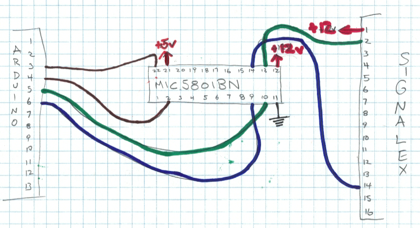
Each segment is controlled by a center tapped coil. The ends of the coil are connected to red and orange wires. The center is a black wire. So each segment has three wires: red, black and orange. Applying a positive voltage between red and black flips the segment one way. Applying a positive voltage between orange and black flips the segment the other way. The red and orange wires are connected to a 16 pin connector. The black leads are crimped together and one black lead goes to the 16 pin connector. One pin on the connector is unconnected.
| Pin | Colour | segment | Pin | Colour | segment | diagram |
|---|---|---|---|---|---|---|
| 1 | black | +12v | 9 | orange | E | 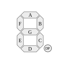 |
| 2 | red | C | 10 | orange | G | |
| 3 | red | D | 11 | orange | F | |
| 4 | red | E | 12 | orange | D | |
| 5 | red | G | 13 | n/c | ||
| 6 | red | F | 14 | orange | C | |
| 7 | red | B | 15 | orange | B | |
| 8 | red | A | 16 | orange | A |
The correct voltage is 12v. Each coil (half coil?) has a DC resistance of about 100 ohms. So the current is about 120 mA. According to the signalex datasheet, current must be applied for 90ms to move a segment.
In theory, it doesn't matter which polarity is applied to the coil. For instance, setting red as +12v and black as ground will work. Setting black as +12v and red as ground will flip the segment the other way. In practice, using the mic5801BN the voltages are important.
The color coding of the signalex wires had me confused for a few hours, but the correct way to use the signalex with the mic5801BN is to connect BLACK to +12v. That's because (when enabled) the mic5801BN outputs actually sink current, that is to say, they become ground. When not enabled, the mic5801BN outputs provide high impedance. So when we enable a mic5801BN output, current flows from the black wire, through the appropriate red or orange wires to ground through the mic5801BN. Pin 12 of the mic5801BN should also be connected to the common +12v.
In this experiment, I used the c segment on outputs 7 and 8 of the mic5801BN. I use four arduino digital outputs: pin 3 controls OUTPUT ENABLE (inverted), pin 4 controls STROBE, pin 5 is the enable line for OUPTPUT8 connected to RED-C and pin 6 is the enable line for OUT7 connected to ORANGE-C.
/***********************************
 *      Name: signalex0
 *      Author: Andrew Howlett
 *      Date: 27 Sep 2013
 *      Notes: using mic5801bn to drive
 *             enable is inverted -> high is disabled, low is enabled
 ***********************************/

int strobe5801 = 4;
int enable5801 = 3;
int seg1Yellow = 5;
int seg1Black = 6;

void setup() {
  pinMode(strobe5801, OUTPUT);
  pinMode(enable5801, OUTPUT);
  pinMode(seg1Yellow, OUTPUT);
  pinMode(seg1Black, OUTPUT);

  //  initialize 5801 - disable it

  digitalWrite(enable5801, HIGH);
  digitalWrite(strobe5801, LOW);
}

void loop() {
  digitalWrite(seg1Yellow, HIGH);
  digitalWrite(seg1Black, LOW);
  delay(1);
  digitalWrite(strobe5801, HIGH);
  delay(1);
  digitalWrite(strobe5801, LOW);
  digitalWrite(enable5801, LOW);
  delay(250);
  digitalWrite(enable5801, HIGH);

  digitalWrite(seg1Yellow, LOW);
  digitalWrite(seg1Black, HIGH);
  delay(1);
  digitalWrite(strobe5801, HIGH);
  delay(1);
  digitalWrite(strobe5801, LOW);
  digitalWrite(enable5801, LOW);
  delay(250);
  digitalWrite(enable5801, HIGH);
}