
|
|
| Click on the image to load full size |
First, I suggest you skip right to the video to see what I'm talking about.
Flip dots are a (mostly) obsolete sign technology. A small disc containing a permanent magnet is mounted on an axle on the top of the device. Underneath is another permanent magnet surrounded by a coil. Passing a current through the coil sets the polarity of the bottom magnet and the magnet in the dot flips over to align its polarity with the bottom magnet. Changing the direction of the current through the coil causes the dot to flip. The magnet is permanent so the dot will stay flipped when the device is unplugged.
Flip dots of different sizes require different voltages and currents. Also, the coil must be energized for a minimum time in order to change the polarity of the bottom magnet. I used a trial and error method to determine the specifications for the flip dots in this experiment. The voltage is 5v, the current is about 50mA and I energized the coils for 100 milliseconds. The dots did not require limiting resistors.
I found these flip dots in a bin at Active Electronics on Queen Street in Toronto. I think the strip of 8 dots cost about $1.50. Three of the dots are broken.
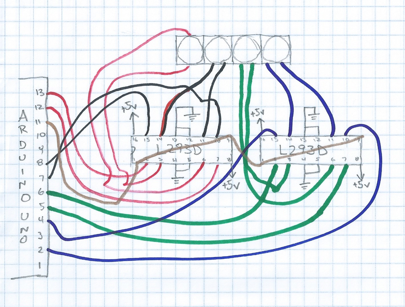
Each dot requires +5v to flip one way and -5v to flip the other way. An arduino output cannot provide -5v so we need a driver of some sort. I decided to use the l293d quad half h bridge chip, because they are well documented and support high current load so I can use the same design to drive bigger flip dots. (Another option MIGHT be the mic5801 which supports eight outputs per chip but I'm uncertain how to wire it for flip dot operation.)
Each l293d chip contains two complete H bridges. That means an l293d can control only two flip dots. So I use two l293d chips to control four dots. Each flip dot requires two control pins from the arduino and two lines between the l293d and the legs of the flip dot. If you look closely at the photo you will see that I color coded the wires for each flip dot: yellow, white, green and blue. I chained together the enable pins for all four bridges. That means I'm sending current through some coils even when the dot might not be changing orientation, but it is way easier than using separate output pins to enable each dot.
/*
  Flip4 - demo for four flip dots/two l293d
 */

int dot1a = 13;
int dot1b = 12;
int dot2a = 8;
int dot2b = 7;
int dot3a = 6;
int dot3b = 5;
int dot4a = 4;
int dot4b = 2;
int enable = 11;

void setup() {
  pinMode(dot1a, OUTPUT);
  pinMode(dot1b, OUTPUT);
  pinMode(dot2a, OUTPUT);
  pinMode(dot2b, OUTPUT);
  pinMode(dot3a, OUTPUT);
  pinMode(dot3b, OUTPUT);
  pinMode(dot4a, OUTPUT);
  pinMode(dot4b, OUTPUT);
  pinMode(enable, OUTPUT);
  setDot(dot1a, dot1b, HIGH);
  setDot(dot2a, dot2b, HIGH);
  setDot(dot3a, dot3b, HIGH);
  setDot(dot4a, dot4b, HIGH);
  enableDots();
}

// the loop routine runs over and over again forever:
void loop() {
  setDot(dot2a, dot2b, HIGH);
  setDot(dot1a, dot1b, LOW);
  enableDots();
  delay(150);
  setDot(dot1a, dot1b, HIGH);
  setDot(dot2a, dot2b, LOW);
  enableDots();
  delay(150);
  setDot(dot2a, dot2b, HIGH);
  setDot(dot3a, dot3b, LOW);
  enableDots();
  delay(150);
  setDot(dot3a, dot3b, HIGH);
  setDot(dot4a, dot4b, LOW);
  enableDots();
  delay(150);
  setDot(dot4a, dot4b, HIGH);
  setDot(dot3a, dot3b, LOW);
  enableDots();
  delay(150);
  setDot(dot3a, dot3b, HIGH);
  setDot(dot2a, dot2b, LOW);
  enableDots();
  delay(150);
}

void enableDots() {
  digitalWrite(enable, HIGH);
  delay(150);
  digitalWrite(enable, LOW);
}

void setDot(int dota, int dotb, int HILOW) {
  if (HILOW == HIGH) {
    digitalWrite(dota, HIGH);
    digitalWrite(dotb, LOW);
  } else {
    digitalWrite(dota, LOW);
    digitalWrite(dotb, HIGH);
  }
}