Diagram 1: My LAN
by Andrew Howlett
April 2002
This document explains how to build a firewall using Linux. The firewall requires the following materials:
A PC to use as the firewall. Minimum system requirements are: Pentium CPU, PCI bus, 16 MB RAM, floppy drive. In theory, a 486 CPU should work fine. The PCI bus is required to support current ethernet cards. No hard drive is required: our firewall will use a write-protected floppy disk for non-volatile memory.
A linux workstation on which to build the firewall software. The workstation should have recent copies of gcc and glibc.
I also assume that you have a basic knowledge of IP networking: how IP addresses work, how IP networks are defined, how to activate and configure interfaces for IP networking.
Packet Filters and ProxiesFirewalls make a simple decision: ACCEPT or DENY. If the communication is permitted, then the firewall ACCEPTs. If the communication is not permitted, then the firewall DENYs. There are two distinct types of firewalls: packet filters and proxies. The difference is what information the firewall uses to make the ACCEPT/DENY decision. The packet filter is the simpler of the two firewalls. The packet filter makes it's decision using four pieces of information: source IP address, destination IP address, IP port number, and source network interface. These information are fully determined by the network card which receives the packet and the IP header, so the packet filter doesn't need to look at the contents of the packet. As a result packet filters are very fast and use few resources. This tutorial will discuss the implementation of a packet filtering firewall using Linux.
It so happens that the firewall described in this lesson has some of the capabilities of a 802.11b wireless access point. Readers should note, however, that the firewall does not behave as a access point as strictly defined in the 802.11b standard.
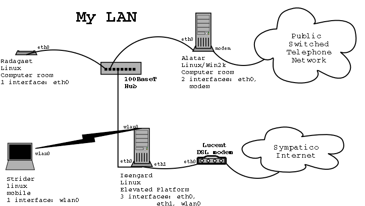
The network diagram summarizes all the information about your network. For small networks, the diagram puts all the info you need in your pocket. For large corporate networks you might need a network management software tool to build and maintain the network diagram. For this tutorial, we will use an example of a small home network.
The network diagram must depict every host, every communication box, every interface, and every wire. For every host the following information must be displayed:
Hostname
Operating System(s)
physical location
number of network interfaces
For each communication box, the following informatin must be shown:
Make, Model
Physical Location
number of network interfaces
For each network interface, the following information must be shown:
Data link protocol
Make/model or chipset
MAC address (ethernet cards only)
IP address or DHCP
This might look like a lot of information: too much to fit on the diagram. In fact, I usually put the interface details on the back of the diagram, and just label the interface names on the diagram. This puts all the information I need to solve 90% of network errors in my pocket. Here are examples of my network diagrams.
|
|
Radagast |
Isengard |
|
Sidebar: MAC AddressEvery ethernet card has a unique Media Access Control (MAC) address. If you use the "ifconfig eth0" command on a system having an ethernet card, then you will see a notation called "Hardware address" followed by a six hexadecimal numbers separated by colon symbols. In most cases MAC address is of no interest to the user or sysadmin, but the Linux netfilter can filter on MAC address. |
Notes:
to enable forwarding:
echo "1" > /proc/sys/net/ipv4/ip_forward
to turn rp_filter off:
echo "0" > /proc/sys/net/ipv4/conf/<device>/rp_filter and echo "0" > /proc/sys/net/ipv4/conf/all/rp_filter
In Linux kernel terminology, packet filtering is called netfiltering. Linux kernel 2.4 uses a netfiltering software called "iptables". This lesson will describe the usage of iptables. The basic idea of packet filtering is that incoming and outgoing IP packets are tested by rules which determine how the packet will be handled. Usually a packet will be tested by a sequence of rules. A sequence of rules is called a "rule chain" or more simply a "chain". There are three built-in chains: INPUT, OUTPUT, and FORWARD.
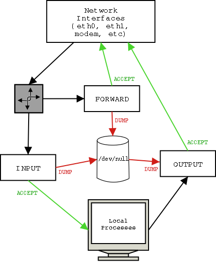
The diagram above shows what's going on in a firewall running iptables. The top of the diagram represents the network interfaces (ethernet cards, modems, ppp, etc). This is where IP packets enter and exit the machine. Packets entering the machine first go to the routing process. The routing process determines whether the incoming packet is destined for a local process (an application running on the firewall machine) or if the packet should be forwarded to another computer. We will discuss dedicated firewall machines, so we will ignore local processes and the corresponding INPUT and OUTPUT chains. For a dedicated firewall, all packets must be forwarded, so we will assume that the packet is routed to the FORWARD chain. The forward chain compares the incoming packet to its preprogrammed sequence of rules. If one of the rules ACCEPTs the packet, then the packet is sent back to the network interfaces to be forwarded to the destination network. If one of the rules DUMPs the packet, then the packet is sent to /dev/null (an electronic trash can). What happens if none of the rules issue an ACCEPT or DUMP command? Then the packet is said to "fall off the end of the chain". For every chain, the sysadmin must define the default action which occurs when a packet falls off the end. The default action for a firewall should be DUMP. Why DUMP? Because the ideology of a firewall should be "If I haven't explicitly accepted the communication, then the communication should be denied."
REMEMBER TO SET THE DEFAULT TARGET FOR EACH CHAIN TO DUMP!
The sysadmin uses the "iptables" utility to configure the packet filtering system. The iptables utility is a command line interface, all the configuration parameters are specified as command-line arguments. The first argument is the "Command". There are commands to configure chains and commands to add and delete rules to chains.
iptables -P chain target [options]
iptables -[LFZ] chain [options]
|
Examples: |
|
|
|
|
|
iptables -P FORWARD DUMP |
dump packets that fall off the end of the FORWARD chain |
|
|
|
iptables -L |
list all rules in all chains |
|
|
|
iptables -F FORWARD |
delete all rules in the FORWARD chain |
|
|
|
iptables -Z FORWARD |
reset the counters in the FORWARD chain |
|
|
|
Policy |
-P |
Set the policy for the selected chain to the given target. Most sysadmins use a policy of denying all communications then permitting authorized communications. Therefore you should use the DUMP target when specifying policy. |
|
|
|
List |
-L |
List the rules in the selected chain. If no chain is selected, then all the rules from all the chains are displayed. |
|
|
|
Flush |
-F |
Delete all rules in the selected chain. |
|
|
|
Zero |
-Z |
Reset the packet and byte counters in the selected chain to zero. If no chain is selected, then the counters for all the chains are reset to zero. |
|
iptables -[ADC] chain rule-specification [options]
iptables -D chain rule-number [options]
iptables -[RI] chain rule-number rule-specification [options]
|
|
Append |
-A |
Append rule to the end of the selected chain. |
|
|
|
Delete |
--D |
Delete one or more rules from the selected chain. The rule to be deleted can be described using a rule specification, or the number of the rule may be specified (the first rule in the chain is rule #1). |
|
|
|
Replace |
-R |
Replace the rule numbered rule-number with the new rule specification. |
|
|
|
Insert |
-I |
Insert a new rule in the chain at the position specified by rule-number. |
|
There are five options which might be used to adjust an iptables command.
|
|
Verbose |
-v |
Causes lots of information to be displayed. Mainly used with the List command. |
|
|
|
Numeric |
-n |
IP addresses and port numbers will be printed in numeric (e.g. dotted decimal) format |
|
|
|
Exact |
-x |
Usually when the list command displays counters the values will be rounded off to the nearest K (1000), M (1000K) or G (1000M). The exact option causes the exact value of the counter to be displayed. |
|
|
|
Line numbers |
--line-numbers |
When listing rules, the line numbers options causes line numbers to be displayed at the beginning of each rule. The line number corresponds to that rule's position in the chain |
|
|
|
Modprobe command |
--modprobe=command |
By default, iptables will use the modprobe utility to load kernel modules. See the "How to compile a kernel" lesson for an explanation of modprobe and kernel modules. The modprobe command option allows the sysadmin to specify a different utility to load kernel modules. |
|
A filter consists of several chains, and a chain is a sequence of rules. So what's a rule? A rule is a set of conditions and an action to perform when all the conditions are met. In iptable lingo, the action to perform is called the "target". When a packet matches the conditions, the corresponding target is immediately performed and any subsequent rules in the chain are ignored.
In this lesson we will only consider the two most important targets: ACCEPT and DROP. ACCEPT means that the firewall has approved the packet for transmission. If a packet is accepted, then the firewall will transmit the packet on the appropriate network interface. DROP means that the firewall has rejected the packet. The packet is "dropped on the floor".
The target is implemented when a condition is matched. A condition is a set of criteria describing the packet. The condition is a set of properties describing the packet. Iptables includes a limited set of match criteria.
|
|
Source address |
-s |
The source IP address of the packet. Typically source address is expressed as a range of values, using the address/netmask notation. For example 192.168.1.0/255.255.255.0 specifies IP addresses 192.168.1.X where X is 0 to 255. |
|
|
|
Destination address |
-d |
The destination IP address of the packet, uses the same format as source address. |
|
|
|
Protocol |
-p |
The protocol which the packet contains, may take the following four symbolic values: TCP, UDP, ICMP, ALL (not case sensitive); or may be specified by a number. The number 0 (zero) is equivalent to ALL. See the /etc/protocols file for a list of protocol numbers. |
|
|
|
In interface |
-i |
The network interface on which the packet was received. For instance, eth0 or ppp0. The symbol "+" is a wildcard. So -i + matches all interfaces, "-i eth+" matches all ethernet interfaces. |
|
|
|
Out interface |
-o |
Similar to in interface. |
|
|
|
Fragments |
-f |
Large IP packets are sometimes broken into smaller fragments for transmission on local networks. The first fragment of an IP packet incluldes the packets IP header, subsequent fragments contain only data. The -f criterion matches the headerless fragments, i.e. The second, third, fourth packets and so on. |
|
Each criteria may be inverted by using the "!" operator. For instance, "-s !192.168.1.0/255.255.255.0 DROP" means "if the packet does not come from my private network 192.168.1, then drop the packet".
The Internet Assigned Numbers Authority (IANA) controls the assignment of IP addresses. The IANA assigns blocks of public IP addresses (IP networks) to governments and corporations. In theory, if a computer has a public IP address then it should be able to send packets to and receive packets from every other computer that has a public IP address. Unfortunately, it is not practical to assign a public IP address to every PC. Therefore the IANA has reserved three IP networks for private networking: 192.168.0.0/16, 10.0.0.0/8 and 172.16.0.0/16. Anyone may use these private IP addresses. Most often, people use the first block: 192.168.0.0/16 and subnet it to several smaller networks such as in the example network (192.168.0.0/24 and 192.168.1.0/24). That is why you will so often see the 192.168.0 network used in tutorials.
The catch with private IP addresses is that they are not allowed to connect to the public internet. For instance, no packet on the Internet may have the source address 192.168.0.1. If you want to connect to the internet from a private network, you must first obtain one public IP address, then you must translate every packet from your private network to a socket on your public IP address. This translation process is called Network Address Translation (NAT) and the NAT function is built into the linux netfilter.
Linux implements NAT within the netfilter system - NAT is an IP table. Configuring NAT table is done the same way as configuring the filter table, but you must use the "-t nat" option to specify the NAT table. For instance, to verbosely list all the rules in the NAT table, use the following command:
iptables -t nat -L -v
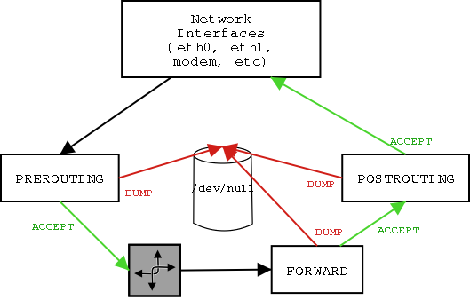
The NAT table contains two chains: PREROUTING and POSTROUTING. Add these two chains to the FORWARD chain which is being implemented for packet filtering, and the diagram below illustrates how IP packets are processed by the firewall.
When we do NAT we want to do two things: first we want to change the source address of outgoing packets. We want to replace the private source IP address with the public IP address belonging to the firewall. This is easily performed with the following command:
[root@Isengard]# iptables -t nat -A POSTROUTING -o ppp0 -j MASQUERADE
Notice that we are adding this rule to the POSTROUTING chain. The POSTROUTING chain is implemented just before the packet leaves the firewall. This is significant for two reasons. First, all the other chains may use the "real" private IP address for their matches. Second, the POSTROUTING chain may perform matches against the output network interface. In the example network, all packets going to the Internet are transmitted over the ppp interface, so the firewall uses the MASQUERADE target against all packets being transmitted on the ppp interface.
NAT has a second function: change incoming destination addresses back to their private IP addresses.
iptables -t nat -A PREROUTING -
We will write a set of rules for the example network. You should review the network diagram . The first thing that we want to do is clear the FORWARD chain and disable all unauthorized communication.
[root@Isengard]# iptables -F FORWARD

[root@Isengard]# iptables -P FORWARD DUMP
Now we have to decide what communication we will authorize. Hosts on the 100BaseT LAN (IP addresses 192.168.0.0/24) are allowed to communicate with hosts on the wireless LAN (IP addresses 192.168.1.0/24), so we accept packets between those networks.
[root@Isengard]# iptables -A FORWARD -s 192.168.0.0/24 -d 192.168.1.0/24 ACCEPT

[root@Isengard]# iptables -A FORWARD -s 192.168.1.0/24 -d 192.168.0.0/24 ACCEPT
Both private networks are allowed to send packets to the Internet, so we accept packets from them to the Internet network interface.
[root@Isengard]# iptables -A FORWARD -s 192.168.0.0/24 -o ppp0 ACCEPT

[root@Isengard]# iptables -A FORWARD -s 192.168.1.0/24 -o ppp0 ACCEPT
We must enable IP masquerading on the network interface leading to the internet.
[root@Isengard]# iptables -t nat -A POSTROUTING -o ppp0 -j MASQUERADE
We will allow packets from the Internet into our private networks, but only when the connection has already been established by one of our own computers. In other words, we don't let any packets into our network, we only allow packets which have been "invited". We will use the NAT table, because we want the NAT module to change the destination addresses to the private network addresses.
[root@Isengard]# iptables -t nat -A FORWARD -m state --state ESTABLISHED,RELATED -j ACCEPT
How to build
We want to put our firewall on a floppy disk. To accomplish this, we must complete two large tasks:
We must build a new kernel and write this new kernel to the floppy
We must build a root filesystem and write the root filesystem to the floppy.
The linux kernel has a very interesting feature: after it boots it can create a ramdisk and copy a filesystem from floppy to the ramdisk. For added value, the filesystem can be stored in a compressed file on the floppy. But first we need to construct the root filesystem. First we zero out the device. This is important, because later we will compress the filesystem and we want to get optimal compression ratios. Then we create a filesystem on the ramdisk.
[root@radagast root]# dd if=/dev/zero bs=1024 count=4096

[root@radagast root]# mke2fs -m0 -b 1024 /dev/ram0 4096
The -m0 option reserves 0% of the filesystem for the superuse (the default is 5%) and the -b 1024 selects the smallest block size (1024 octets) to obtain the most efficient use of RAMDISK capacity.
We need to mount the root filesystem somewhere:
[root@radagast root]# mkdir /mnt/ramdisk

[root@radagast root]# mount -t ext2 /dev/ram0 /mnt/ramdisk
Now you can build the root filesystsem at /mnt/ramdisk. First you have to make the basic set of directories: /bin, dev, /etc, /lib, /proc, /tmp, /usr, /var. We don't need a /home directory, since this machine will have no user accounts. And you can remove the /lost+found directory.
cd /mnt/ramdisk

mkdir bin dev etc lib proc tmp usr var

rm -f -r lost+found
We need to create the device special files in the /dev directory. We will cheat: we will copy the files from the build computer to the ramdisk.
cd /mnt/ramdisk/dev
cp -dpR /dev/{ttyS[01], eth[01], ram[01], null, stdin, stdout, stderr} /mnt/ramdisk/dev
| /bin |
init, getty or equivalent, login, mount, some shell capable of running your rc scripts, a link from sh to the shell |
|
| /dev |
ttyS[01], eth[01], ram[01], null, stdin, stdout, stderr |
cp -dpR /dev/{ttyS[01], eth[01], ram[01], null, stdin, stdout, stderr} /mnt/ramdisk/dev
|
| /etc |
fstab, inittab, passwd, ??? group, shadow, termcap ??? |
|
| /lib |
glibc, |
4.3.4. /lib In /lib you place necessary shared libraries and loaders. If the necessary libraries are not found in your /lib directory then the system will be unable to boot. If you're lucky you may see an error message telling you why. Nearly every program requires at least the libc library, libc.so.N, where N is the current
version number. Check your /lib directory. The file libc.so.N is usually a symlink to a filename
with a complete version number:
+----------------------------------------------------------------------------------+ In this case, you want libc-2.1.1.so. To find other libraries you should go through all the
binaries you plan to include and check their dependencies with ldd. For example: |
| /proc |
no files |
|
| /tmp |
||
| /usr |
||
| /var |
Next we need to populate the /etc directory. We need the following files.
cd /mnt/ramdisk/dev
cp -dpR /dev/{ttyS[01], eth[01], ram[01], null, stdin, stdout, stderr} /mnt/ramdisk/dev
When you are finished building the root filesystem unmount the filesystem, copy the ramdisk to a file, and zip the file. You might also want to free the ramdisk.
[root@radagast root]# umount /mnt/ramdisk

[root@radagast root]# dd if=/dev/ram0 of=initrd bs=1024 count=4096

[root@radagast root]# gzip -9 initrd

[root@radagast root]# freeramdisk /dev/ram0
The Linux Bootdisk HOWTO
Network Boot and Exotic Root HOWTO
This lesson did not discuss all the capabilities of the iptables utility. Read the iptables man page and write down the commands to create a new chain called "MY_CHAIN" and the command to delete the chain "MY_CHAIN".
iptables man page, Rusty Russel et al, 11 August 2000
IP Tables Tutorial v1.1.9, Oskar Andreasson 2001
Linux 2.4 Packet Filtering HOWTO, Rusty Russel et al, 19 Feb 2002
Linux 2.4 NAT HOWTO, Rusty Russell et al, 19 Feb 2002
The Internet uses 32 bit IP addresses. The IP address has two parts: the first part is the network address and the second part is the host address. Some networks have more hosts than others, so some networks need more hosts addresses than other networks. Therefore the number of bits used for the network and host parts is different on different networks. So there must be a way to define which part of the IP address is the network address and which part is the host address. Actually, there are two ways.
Netmask notation is the older way of specifying network addresses. It consists of two parts: a 32 bit IP address and a 32 bit mask. The mask specifies which bits in the IP address are used for network addressing and which bits are used for hosts addressing. This works by lining up the bits in the IP address and the mask. If the mask bit is "1", then the corresponding bit in the IP address is part of the network address. Usually the IP address and mask are written in dotted decimal format, e.g. 192.168.0.0/255.255.255.0. The following table converts the dotted decimal format to binary to better illustrate what the mask means.
|
192 |
168 |
0 |
0 |
||||||||||||||||||||||||||||
|
1 |
1 |
0 |
0 |
0 |
0 |
0 |
0 |
1 |
0 |
1 |
0 |
1 |
0 |
0 |
0 |
0 |
0 |
0 |
0 |
0 |
0 |
0 |
0 |
0 |
0 |
0 |
0 |
0 |
0 |
0 |
0 |
|
|
|
|
|
|
|
|
|
|
|
|
|
|
|
|
|
|
|
|
|
|
|
|
|
|
|
|
|
|
|
|
|
|
192 |
168 |
0 |
0 |
||||||||||||||||||||||||||||
You can see from the table above that the mask clearly shows which bits in the 32 bit address are used for the network address. In this example, the first 24 bits are used for the network part and the network address is 192.168.0. The host part of the address is 8 bits long. So specifying a source address of -s 192.168.0.0/255.255.255.0 will match 256 different IP addresses: 192.168.0.0, 192.168.0.1, 192.168.0.2, 192.168.0.3, ..., 192.168.0.255.
You might notice that the mask in the example above consists of 24 ones followed by eight zeros. An obvious shortcut is to specify the network as 192.168.0.0/24 (we don't have to specify the number of zeros because the number of ones plus the number of zeros always adds up to 32). This is called Classless Interdomain Routing (CIDR) notation. CIDR notation is the modern way of writing network addresses.