Mandatory Warning. This document describes an experimental procedure. It worked for me, but I don't guarantee it will work for you. Be prepared to buy a new TV set.
The C64 video output circuitry is detailed here and the output connectors are detailed here.
The input connector for S-Video is detailed here.
Although it's not really necessary, here is a graphic of the C64 A/V plug. Note that the early version of the C64 only has pins 1 to 5. Note also that the metal housing of the A/V plug is grounded.

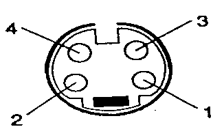
The S Video plug (male) looks like this

1 - Chroma ground
2 - Luma ground
3 - Chroma
4 - Luma + sync
So the objective is to create a patch cable that goes something like this:
| C64 Pin | S-Video Pin | ||
| 2 | 1 | ||
| 2 | 2 | ||
| 4 or 6 | 3 | ||
| 1 | 4 |
If you have an early C64, you must use pin 4 as your chrominance signal. If you have a later 8 pin A/V connector, then you can use pin 6.
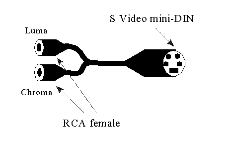
I already have a C64 to 1702 monitor cable. This cable breaks the C64 A/V port into three RCA jacks: audio, chroma, and luma (sync on luma). So I will cheat. I will make a crossover cable. The aim of the crossover cable is to take the RCA luma and chroma inputs from my C64 cable and cross the conductors to the S Video mini DIN output. I will do this by cutting up a pair of old RCA cables and a S-Video cable. The resulting crossover cable looks like this:

This is not to scale - my cable is about 10 feet long and works great. It gives a really crisp picture on a 27" TV set. Better than my old 1702 monitor. later, Andrew.